Figure 1 from Prototype design of smart home system using internet of Circuit Diagram Curriculum (Series) Works With 2020: How to Build a Sensor. This training provides a walkthrough of an IoT sensor project via Simplicity Studio. Engineers will leave knowing the best path to get started designing.

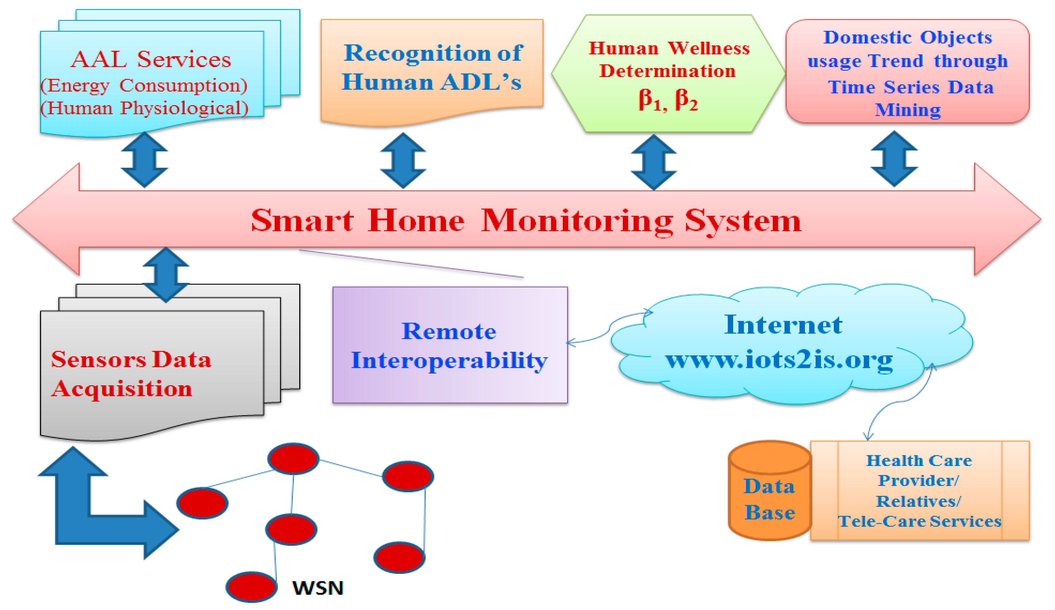
The Things Network allows to create applications to exchange data with your devices — often referred to as nodes as well — as shown here. In my case, my goal was to create this simple unidirectional data flow: device -> gateway -> network server -> application server. In short, I took the following steps to achieve it: I signed up on TTN Wireless Sensor Network (WSN), is an infrastructure-less wireless network that is deployed in a large number of wireless sensors in an ad-hoc manner that is used to monitor the system, physical, or environmental conditions. Sensor nodes are used in WSN with the onboard processor that manages and monitors the environment in a particular area. The foundation of any smart home system lies in its network infrastructure and smart devices. Most smart devices rely on WiFi connectivity, although some also support wired connections. Prior to setting up your smart home system, ensure you have a stable and robust WiFi network coverage in your environment. Motion Sensor . Tapo T100

How to Build an IoT Sensor Tutorial Circuit Diagram
Sensor networks are no longer expensive industrial constructs. You can build a simple sensor network from easily procured, low-cost hardware. All you need are some simple sensors and a microcontroller or computer with input/output capabilities. Yes, your Arduino and Raspberry Pi are ideal platforms for building sensor networks.
The sensor comes with a 10k ohm resistor that connects the data pin to power as a pull up resistor while another wire connects it to GPIO D3. Be careful to follow the setup below and make sure you double check the datasheet for the sensor and RF module to ensure that the components are positioned in the breadboard properly and the power, ground, and signal pins are connected to the right pins. A smart sensor network consists of multiple sensors that collect data from their surroundings. These sensors can measure temperature, humidity, light, motion, and more. The data collected is sent to a central system for analysis. This setup is useful in various applications, such as smart homes, industrial automation, and environmental

How To Build A Smart Home (Beginner Guide 101) Circuit Diagram
The project uses a Seeed XIAO ESP32C6 to build a low-cost, Wi-Fi-enabled sensor, ideal for applications where you need remote environmental monitoring. It includes instructions to set up a temperature, RSSI, and battery voltage sensor using MQTT to relay data to a Home Assistant setup or similar platform.